You have no items in your shopping cart.
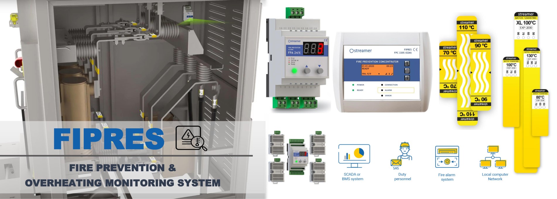
FIRE PREVENTION SYSTEM
Key Benefits
- 24/7 control of concerning points in LV and MV electrical panel of any configuration
- Detects hot spots long before a dangerous situation arises, hence avoiding material damage, stop of production process and threats to life
- Increases equipment safety and reliability of operation
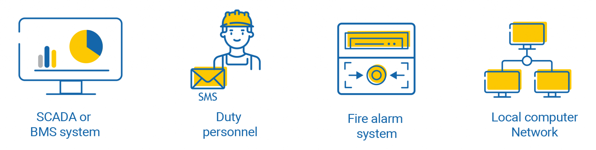
- Can be integrated to SCADA/BMS and local alarm systems
- Quick and easy installation even for existing systems
Problem
Every year fire causes an enormous amount of damage to all kinds of facilities, social and private possessions. It can lead to life threatening incidents and huge losses because of material damage of assets, power supply interruption, production loss and business opportunity cost. Global statistics show that around 30% of the fires are caused by electrical faults:
25% – of building fires are due to electrical malfunctions according to European Fire Academy (EFA)
32% – of fires in Germany are related with electricity according to German Insurance Association
3,2B – USD annual cost of damage in the U.S. and Europe due to electrical fires according to the National Fire Protection Association (NFPA) and the European Fire Safety Alliance (EFSA)
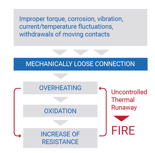
In practice, the most common cause of fire and damage to equipment in electrical panels are loose connections, especially those made on site. The connection may become loosened due to improper tightening torque during assembly, constant vibration, corrosion or mechanical wear of moving contacts, such as withdrawable contacts of a circuit breaker. Another reason which can lead to a worsening of the contact condition is temperature cycling through the day. Heating at high current and cooling at low current causes expansion and contraction of contact and may lead to contact loss. And even if an insufficiently tightened connection can still provide an acceptable level of mechanical reliability of the connection, it worsens electrical and thermal reliability:
- As soon as the connection is loosened, its own resistance increases. This happens due to loosening the fit of contact surfaces (Bolt / Busbar, Cable lug / Busbar, etc.) This resistance causes the contact to heat up
- Heating due to increased resistance contributes to the oxidation process (which happens faster at higher temperatures)
- Oxidation covers the contact with an oxide film, and its resistance is much higher than for the base metal
- The resulting thermal runaway leads to a complete failure of connection. As a result, such contact burns out or leads to an electric fire in the compartment
FIPRES. How It Works?
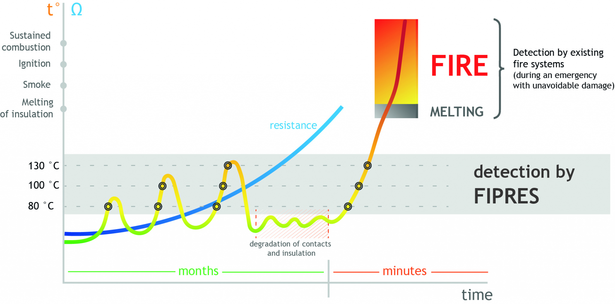
FIPRES works on principle of early detection. Indeed, usually fire starts with melting of cable insulation, which is the weakest point in terms of withstanding temperature. Depending on the material and thickness, generally there are 2 critical temperatures for cable insulation: 200 °C, when insulation to deteriorate and 280°C, when insulation material starts to melt and smoke. FIPRES works way below these temperatures, providing detection of overheating in a range 80...130 °C, which are abnormal temperatures for electrical equipment, but still months before any dangerous situation.
Typical scenario of fire inside electrical cabinets is shown below:
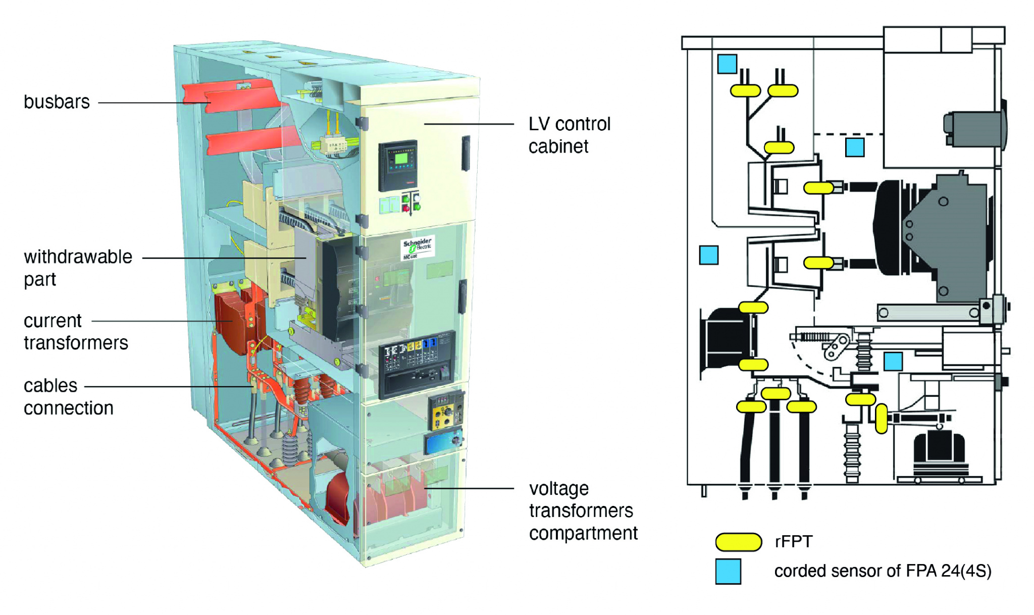
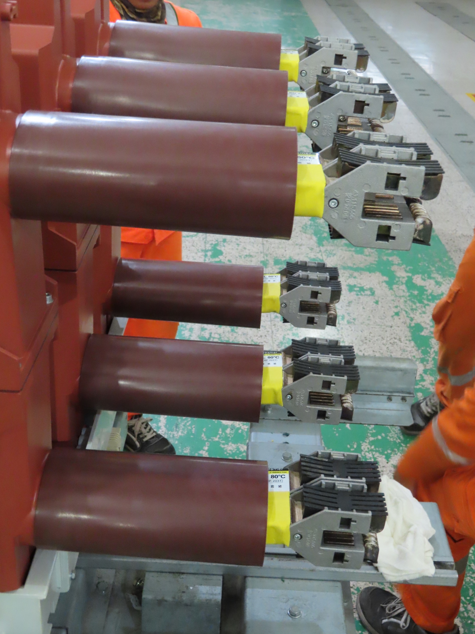
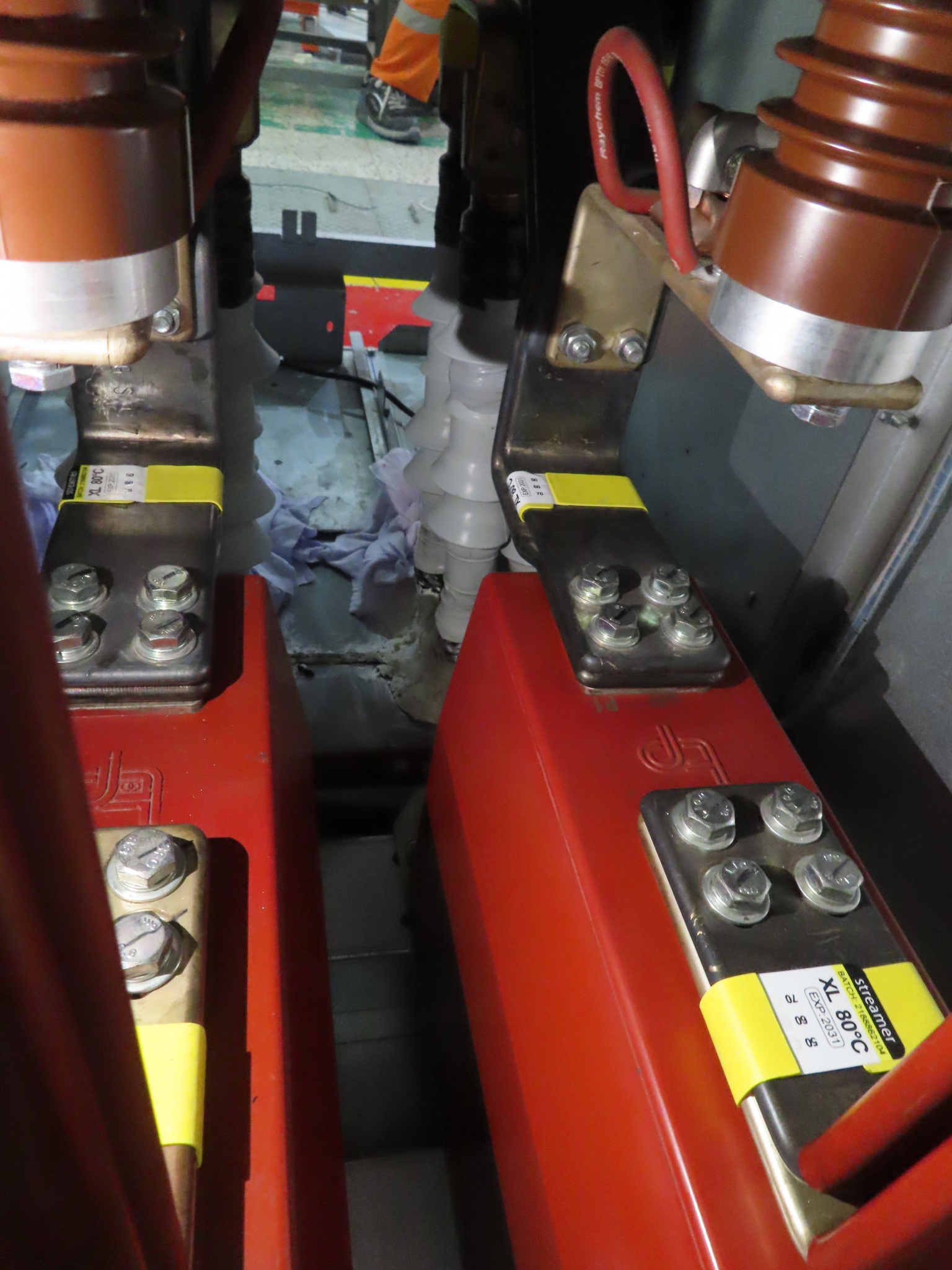
The technology involves the placing of self-adhesive temperature sensitive labels (rFPT) on connection points (busbar contacts, cable lugs, contacts of circuit breaker, fuses, current transformer etc.) inside LV or MV electrical panel of any configuration.
Remote fire prevention thermolabel rFPT
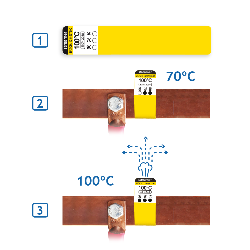
- 1. rFPT must be wrapped around cables/busbars close to the contact points. A gas sensor (FPA) should be installed into the same volume
- 2. Each rFPT has thermo-indication dots with 3 levels of indication. When a contact is heated above 50°/70°/90 °C thermoindication dots irreversibly change their colors to black. It gives clear indication to the inspection team regarding what temperature has been reached since installation of the label.
- 3. In emergency situations when the temperature rises above 80°/100°/130 °C the sticker releases signal gas which is detected by the gas sensor FPA
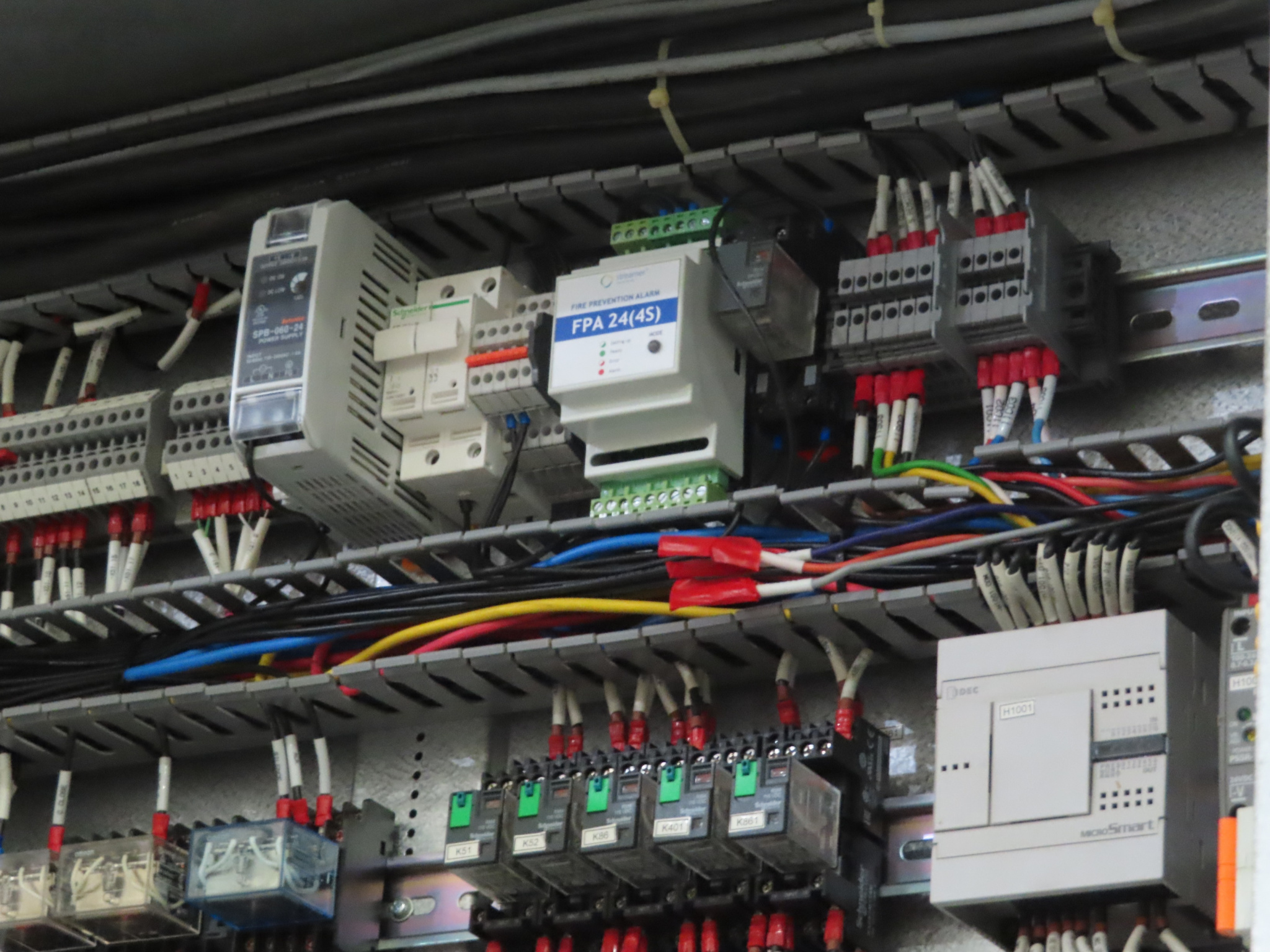
When the contact reaches the activation temperature of the rFPT, the label emits non-toxic and non-flammable signal gas which is detected by special gas sensor (FPA) located in the same compartment as the rFPTs. Immediately after that FPA transmits an ALARM signal to SCADA or BMS system by Modbus or to any other external system via dry contact output.
Fire prevention alarm FPA
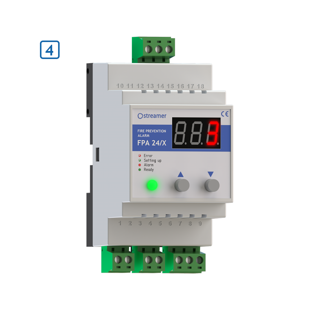
- 4. FPA (after detection of the signal gas) goes into ALARM mode and transmits alarm signal to SCADA or BMS system through Modbus RTU, or to local alarm systems using dry contact output. FPA can be installed both in LV and MV electrical panel.
Fire prevention concentrator FPC
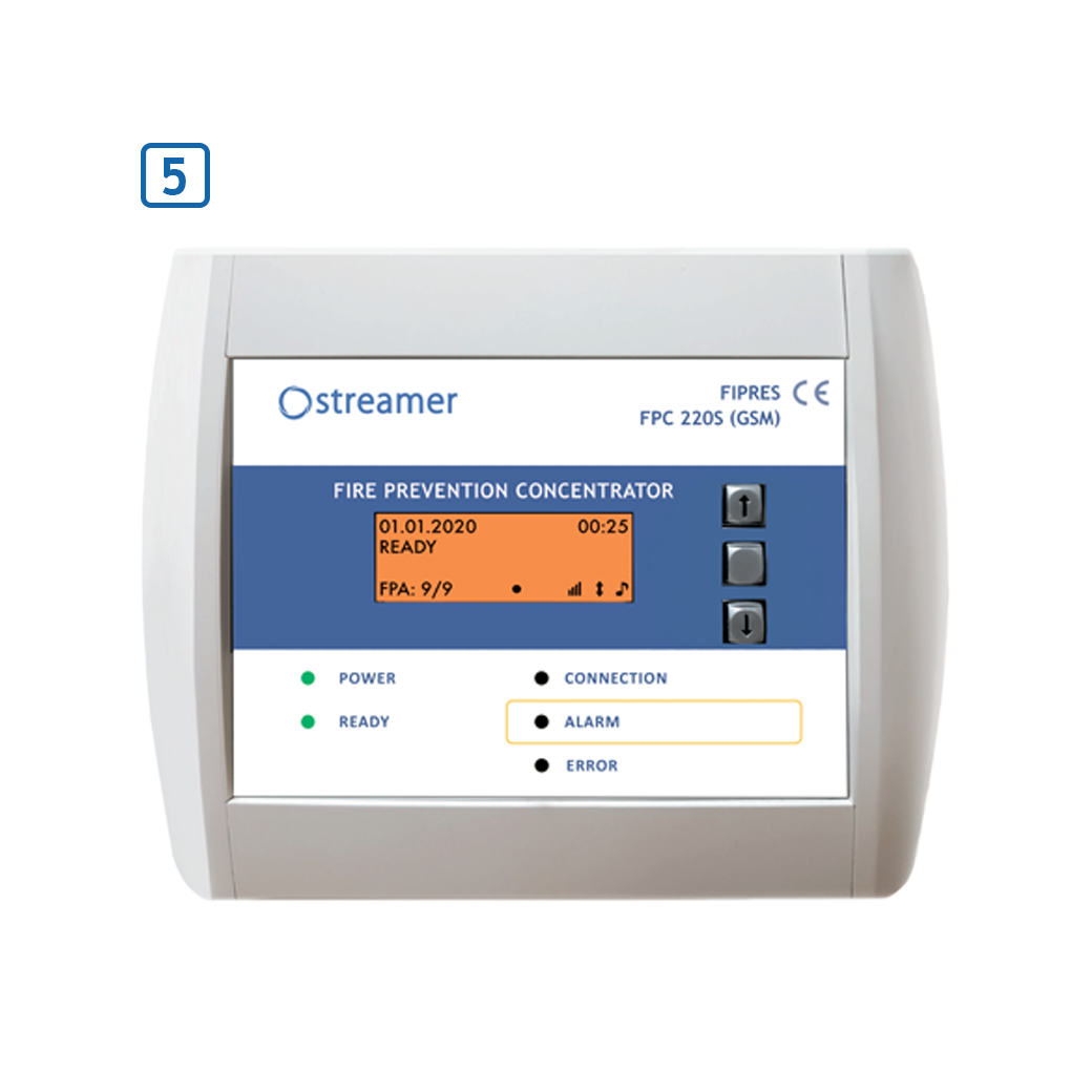
- 5. FPС monitors the status of up to 32 FPA, displays and records Alarm signals. When FPA is triggered, the FPС transmits information to the central fire alarm system, SCADA or BMS. FPA has a speaker for audible notification
- You can use a similar device which supports RS 485 Modbus instead of FPC (or even use light version of FIPRES: only rFPT + FPA. In this case FPA transmits signal directly to SCADA/BMS)
Technical Comparison With Thermal Imaging Control
Regularly checking contact connections is complex due to their large number, the constant operation under-voltage, and often the lack of access for the inspection. The most popular method - scheduled infrared thermography inspections has several significant disadvantages.
- Works around the clock
- Allow to check equipment in locked (explosion-proof) enclosures
- Checks all spots at the same time
- Does not depend on the human factor
- Works only at the time of inspection
- Doesn’t allow to check equipment in locked (explosion-proof) enclosures
- The load at the time of inspection should be at least 60% to see weak points
- Depends on the human factor
- Risky for personnel because the inspection should be done near to live electrical equipment
Scope of application
FIPRES can be used in:
- Low/medium voltage electrical panels
- Switchgear cells
- Any electrical equipment, including equipment in explosion-proof housings
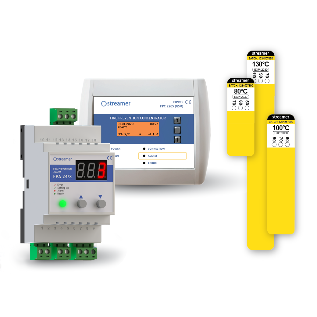
rFPT - remote Fire Prevention Thermolabel
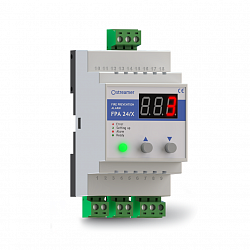
FPА – Fire Prevention Alarm
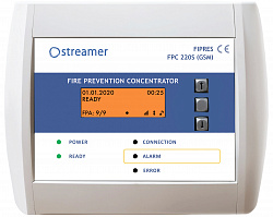
FPC – Fire Prevention Concentrator
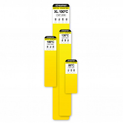
vFPT – visual Fire Prevention Thermolabel
FIPRES consists of 3 main products (rFPT, FPA and FPC), which work together and provide information regarding the dangerous overheating remotely through SCADA system and discrete output. There is an auxiliary product – vFPT, which allows the maintenance team to increase the efficiency of scheduled visual inspections.
rFPT – remote Fire Prevention Thermolabel
rFPT is a thermolabel that has 2 parts: visual indicative part (white) and yellow part with encapsulated safe signal gas, releasing at a certain temperature. This thermolabel is intended to be glued close to electrical contacts prone to be loosened.
The visual indicative part has 3 or 4 white dots, which turn black as soon as contact reaches a certain temperature level. Each dot has a different temperature of activation, allowing to know which exactly degree of overheating happened.
Material with signal gas has a foam structure with tiny capsules with signal gas inside. This gas is colorless, non-toxic for humans and the environment, chemically stable, which means that it doesn’t react with other chemicals or coatings inside the electrical panel.
The validity period of rFPT is 10 years, but we recommend replacing it with a new one after each operation.
FPA – Fire Prevention Alarm
FPA is a gas sensor. It’s intended to detect a concentration of signal gas higher than an activation threshold. It can be connected to the SCADA system thanks to an integrated Modbus interface. There are 2 types of FPA: FPA 24/X (0.1, 0.3, 1) and FPA 24(4S). The main difference between these devices is the number of gas sensors. FPA 24/X has only one gas sensor located inside the case of FPA. Meanwhile, FPA 24(4S) has 4 corded sensors, while the body is used only to hold the processor and logic board. FPA 24(4S) ’s main advantage is that it can be used for large switchgear with few separated compartments (e.g., busbars compartment, incoming cables compartment, CB compartment, etc.)
FPC – Fire Prevention Concentrator
FPC is a hub to work simultaneously with up to 32 FPAs. It’s more convenient to use if you have no SCADA system because the maintenance team can observe events log and status information from a display. FPC has a speaker for audible warning and a GSM module to send ALARM message to duty personnel's cellphone. As well as FPA, FPC can be connected to SCADA and be a transmitter in chain FPAs-FPC-SCADA.
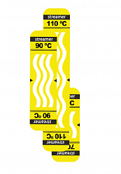
vFPT – visual Fire Prevention Thermolabel
The easiest product in FIPRES range is vFPT. It’s a thermolabel with 3 wave-shaped white curves. As well as thermoindication dots, these curves irreversibly turn and stay black after reaching activation temperature. vFPT is intended to use indoor and works as a perfect assistant to the inspection team since it can be glued in every point of the electrical panel and hold information about overheating between 2 visual inspections, thanks to the one-time principle of activation.
The main field of FIPRES application is electrical panels e.g., switchgears, distribution boards, capacitors bank panels, etc. with up to 3 m3 of volume.
Typical points, required the maximum of attention are:
- Circuit breaker contacts
- Incoming/outcoming cables connection
- Capacitor banks
Other points in particular cases could be:
- Current and voltage transformers
- Transportation joints
On of the advantage of FIPRES comparing to devices with a similar purpose is the ease of installation even when it comes to retrofitting. It’s possible to equip all concerning points of equipment without compromises.
How overheating in electrical equipment happens?
Overheating in electrical compartments is a common occurrence. Possible reasons can include a loose connection, wrong selection of equipment/cross-sections, and overloads. But even overload cannot lead to a fire if all connection points are fine and there are no decent contact resistances across the circuit, which brings us to the problem of loose connection again.
A loose connection can appear because of following reasons:
1. Improper tightening during assembly
2. Vibration over time
3. Large number of connection operations (especially for withdrawable contacts)
4. Repetitive heating and cooling process over time
Since the connection is loosened, it starts to generate excessive heat because of increased resistance. Another possible threat, in that case, is oxidation, which is accelerated by overheating. Oxidation, in turn, covers the contact with an oxide film, which has significantly higher resistance than the base metal. As a result, the contact becomes degraded, and every overload now can lead to a fire.
What temperature is needed for an ignition?
Usually, the weakest point in terms of heat resistance is cable insulation. It starts to lose dielectric properties at 170-200°C; after 280°C, it can begin to melt and smoke. Other points that need to consider are plastic of epoxy enclosures of current/voltage transformers, fuses, and capacitors banks.
Why is thermography inspection not the best solution for your equipment?
Nowadays, scheduled infrared thermography is the primary solution for inspection and reducing risks of fire. Nevertheless, this method has serious flaws:
1. Scheduled basis.
The period between two inspections can be measured in weeks or months. Of course, it doesn’t allow maintenance personnel to be up to date regarding equipment conditions 24/7. Moreover, the scheduled date and time of inspection can be unlucky, e.g., a period of low load, which doesn’t show the full picture regarding equipment conditions. The minimum load should be at least 60% on average to be able to see overheating.
2. Limited or no visibility during an inspection.
Inspection of most of the electrical panels is being done from one single angle. In case of a complex internal layout of the panel, it’s impossible to check all concerning points and make the correct conclusion.
The situation is even worse when it comes to MV equipment since it is not advisable to open the cabinet during its operation. Thus, it’s not possible to check the condition and prevent dangerous situations at all. Solutions like infrared windows can solve this problem only, particularly keeping the problem of limited visibility.
3. Human factors and risk for personnel.
The quality of the report and understanding of equipment conditions also depend on the quality of the inspection team's service. A person, the inspector, can make wrong decisions or even skip some inspection program points. On top of that the survey implies the immediate proximity of the inspector to live parts that pose a real threat to life and health.
How rFPT works?
rFPT is made of composite material with special signal gas inside, which is encapsulated so that it releases gas only at certain temperature. After releasing, the gas spreads over the electrical cabinet, making concentration detectable by FPA. There are 4 different sizes of rFPT. Each size has a different amount of gas encapsulated in it to make proper concentration in the corresponding volume. Every rFPT has 3 or 4 thermoindication dots with varying activation temperatures, which irreversibly turn black after reaching activation temperature.
Is the gas in rFPT dangerous for the environment, humans, or equipment?
No. The gas we use is non-toxic, it’s chemically stable and doesn’t react with other chemicals inside the cabinet and coatings of equipment. This signal gas has no flash point, which means it cannot explode at any concentration. On top of that rFPT generates minimal concentration in overall air composition (0.025% - 0.1% of gas presence in air after releasing). But thanks to selective gas sensors, this amount is more than enough to detect and give ALARM signal.
How do we ensure that rFPT validity period is 10 years?
Encapsulation. It’s needed not only burst at certain temperatures and release gas inside but also to protect gas from diffusion over time. Using the scientific approach (we put rFPT inside the climatic chamber for several months and precisely measure the material's weight loss, which might indicate that gas is being released). These tests are done at different temperature levels and all the results we’ve got tell that even after 10-15 years, there will be enough gas to trigger FPA properly.
How good the adhesion of rFPT?
We use an extra adhesion glue layer from 3M company. Thanks to this and thanks to the low weight of sticker, rFPT will be reliably glued to all 10 years of validity. For sure, adhesion depends on both surfaces, so we highly recommend to clean and degrease the surface before gluing rFPT. Moreover, we recommend gluing rFPT in a ring (with overlap) to provide maximal reliability.
Is the gas lighter than air?
At the initial moment, when it is just released from rFPT, the gas is hot and it’s lighter than air hence it moves from bottom to top. As soon as it’s cooled by ambient air it gets heavier than air and might go down (if it wasn’t dispersed yet). Thus, we recommend placing FPA at the top side of the compartment to detect gas faster since it moves upwards.
Do I need to replace rFPT after its operation?
Even if the rFPT still remains some residual gas inside, we cannot be sure that it will be enough for the next triggering. Please, make a required repair for the overheated spot and replace rFPT sticker with a new one.
How can I understand that rFPT has been triggered?
By checking thermoindication dots. If all the dots are black, this indicates that this rFPT most likely operated.
What rFPT (80, 100, or 130 °C) to choose?
From a technical perspective, the main concerns in terms of fire safety in electrical switchgear are possible deterioration of cable insulation, leading to flashover or melting and further ignition.
Typical materials for cable insulation, such PVC / XLPE / EPR, are subject to degradation, which starts at 170-200°C. After 200°C, it starts changing color, and at approximately 280-300°C, it starts to smoke and melt, leading to a fire. From this point of view, the threshold temperature of ALARM should be less than 130-140 degrees to prevent the cable from negative consequences.
From another hand, there are electrical standards. The main standards describing this issue are IEC 62271-1 (for MV switchgear) and IEC 60947-1 (for LV switchgear). Unfortunately, standards do not give us absolute temperatures, which are more important in terms of fire safety. According to them, bare cooper bolted connections temperature and terminals temperature rise shouldn’t exceed 50-65 degrees compare to ambient air temperature in the enclosure, which means 90-105 degrees of absolute value at 40°C of ambient temperature. For ambient temperature as 50°C (which is normal temperature for most switchgears in countries with warm climate) these limits are 100-115 degrees.
If we combine these two approaches and consider that absolute values are more important than relative values of temperature rise, the best pick will be 100 °C for most of the cases. It’s even better than 80°C rFPT since the 80°C might be reached if the high load met hot ambient temperature, but it will not be a dangerous condition for the equipment. 80 and 130°C products should be used only in specific projects with a defined purpose.
What might the maximum distance between rFPT and FPA be?
From the point of view of detection reliability, this does not really matter. Two factors are needed to ensure only:
1. Correct rFPT size and FPA model (volume dependent)
2. Correct placement of the FPA inside the compartment. Ensure that the FPA is positioned above the rFPT and that there are no obstacles to signal gas to reach the FPA.
Placing the FPA closer to the rFPT only makes sense to increase the detection rate, but 80, 100 and 130 degrees are not emergency temperatures, and this is not a big difference between 10 or 40 seconds of the detection time.